Lectura de pt.asm y uso de la biblioteca desde CReading pt.asm and using the library from C
/* Fragmentos del programa que queremos escribir */sw1 = ptConfigura(1, 1, PT_ENTRADA_PULLUP | PT_ACTIVOBAJA);led1 = ptConfigura(1, 0, PT_SALIDA); /* Dentro del bucle principal */ptEscribe(led1, ptLee(sw1));

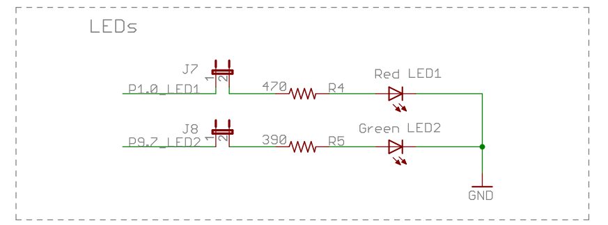
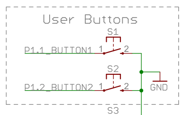
LED1: P1.0 LED2: P9.7SW1: P1.1 SW2: P1.2Los LEDs se activan en alta. Los pulsadores cierran a masa: se leen como activos en baja.
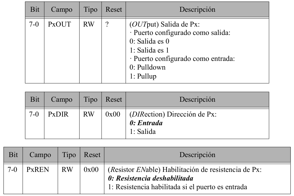
/* Pulsador de la placa: conecta P1.2 a GND */PT_ENTRADA_PULLUP // Fijar el nivel en reposo.PT_ACTIVOBAJA // Interpretar 0 como pulsado. /* Después de configurar el pin */int pulsado = ptLee(sw2);bic.b #BIT2, &P1DIRbis.b #BIT2, &P1RENbis.b #BIT2, &P1OUT
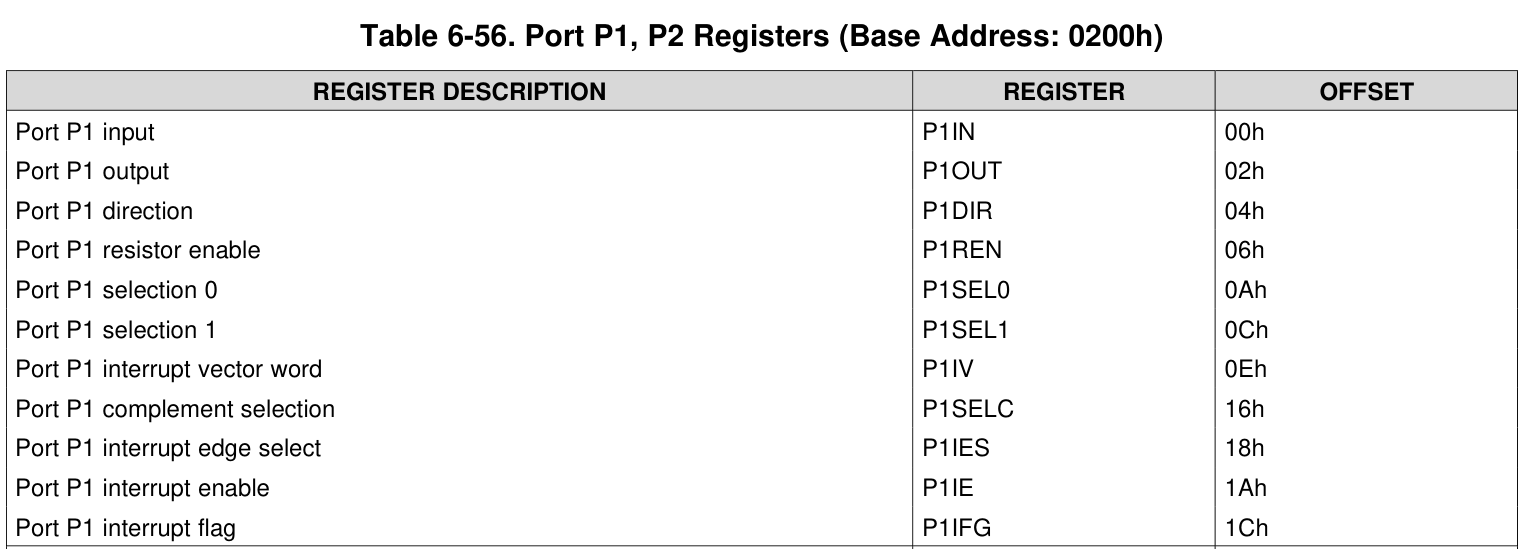
bic.b #BIT2, &P1DIRbis.b #BIT2, &P1RENbis.b #BIT2, &P1OUT.cdecls C,LIST,"msp430ports.h"SW2_BIT .equ BIT2SW2_PORT .equ P1IN bic.b #SW2_BIT, &SW2_PORT+PDIRbis.b #SW2_BIT, &SW2_PORT+PRENbis.b #SW2_BIT, &SW2_PORT+POUTpuerto_t ptConfigura(int puerto, int bit, uint8_t modo); sw2 = ptConfigura(1, 2, PT_ENTRADA_PULLUP | PT_ACTIVOBAJA); /* R12=1, R13=2, R14=modo; retorno en R12 */#define PIN 0#define POUT 2#define PDIR 4#define PREN 6#define PSEL0 0x0A#define PSEL1 0x0C
TabPuertos: .short PJIN .short P1IN .short P2IN ; ... hasta P10IN mov.w R12, R11rla.w R11mov.w TabPuertos(R11), R11TabBits: .byte BIT0 ; 0000 0001 .byte BIT1 ; 0000 0010 .byte BIT2 ; 0000 0100 ; ... hasta BIT7 mov.b TabBits(R13), R15; R12=1, R13=2: queremos configurar P1.2mov.w R12, R11rla.w R11mov.w TabPuertos(R11), R11mov.b TabBits(R13), R15 bic.b R15, PDIR(R11)bis.b R15, PREN(R11)bis.b R15, POUT(R11)sw2 = ptConfigura(1, 2, PT_ENTRADA_PULLUP | PT_ACTIVOBAJA | PT_BAJADA | PT_IRQ); /* modo = 0xE1 */
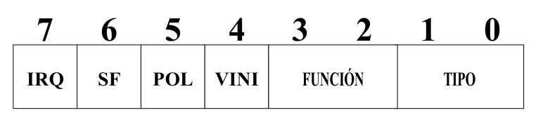
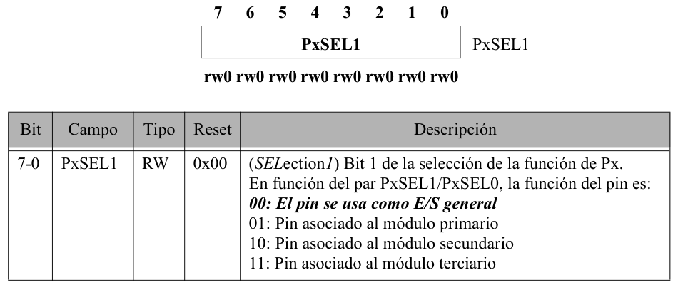
typedef uint8_t puerto_t; sw2 = ptConfigura(1, 2, modo);/* sw2 = 0x8A: polaridad baja, puerto 1, bit 2 */ int pulsado = ptLee(sw2);ptConfigura: cmp.w #MINP, R12 jl ptConfErr cmp.w #MAXP+1, R12 jge ptConfErr and.b #0x07, R13 push.w R12 ; continúa la creación del descriptorptConfErr: mov.w #-1, R12ptConfFin: retrla.w R12mov.w R12, R15rla.w R12rla.w R12add.b R13, R12bit.b #MD_POL, R14jz ptConf1bis.b #BIT7, R12; R12=descriptor, R15=2*puerto, R13=numero de bitptConf1:mov.w TabPuertos(R15), R15mov.b TabBits(R13), R13 ; A partir de aquí: R15=base y R13=mascaraptConfFunc: bit.b #MD_FUNC0, R14 jz ptResetSel0 bis.b R13, PSEL0(R15) jmp ptConfSel1ptResetSel0: bic.b R13, PSEL0(R15)ptConfSel1: ; el mismo patrón para MD_FUNC1 y PSEL1
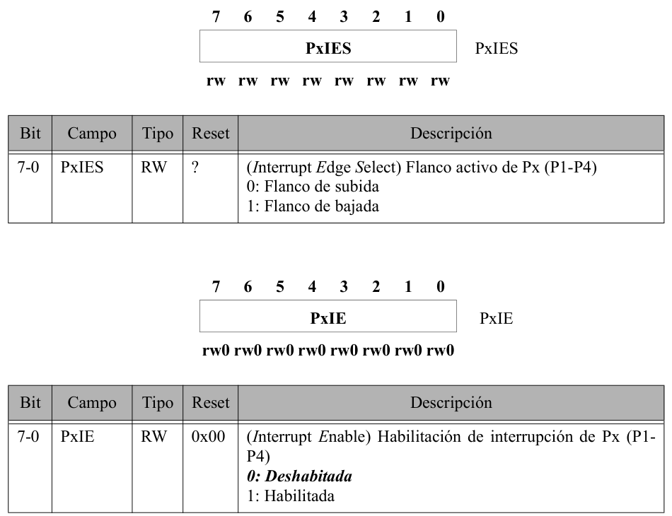
ptConfDir: mov.b R14, R11 and.b #MD_TIPO, R11 rla.b R11 add.w R11, PC jmp ptConfEnt jmp ptConfEntPU jmp ptConfEntPDptConfSal: ; comienza el bloque de salidaptConfEntPU: bic.b R13, PDIR(R15) bis.b R13, PREN(R15) bis.b R13, POUT(R15) jmp ptConfSF ptConfEntPD: bic.b R13, PDIR(R15) bis.b R13, PREN(R15) bic.b R13, POUT(R15) jmp ptConfSFbit.b #MD_POL, R14jz ptConf1bis.b #BIT7, R12xor.b #MD_VINI, R14 ; El bloque de salida usará el VINI ya ajustado.ptConfSal: bit.b #MD_FUNC, R14 jnz ptConfSalF bit.b #MD_VINI, R14 jc ptConfSal1ptConfSal0: bic.b R13, POUT(R15) jmp ptConfSalFptConfSal1: bis.b R13, POUT(R15)ptConfSalF: bis.b R13, PDIR(R15)ptEscFlanco(sw2, 1); // IES: detectar bajada.ptBorraIRQ(sw2); // IFG: quitar lo pendiente.ptEscHabIRQ(sw2, 1); // IE: permitir esta fuente. /* Solo cuando todo el sistema esté preparado: */_EINT(); // GIE: permiso del procesador.ptConfFS: bic.b R13, PIES(R15) jmp ptConfIEptConfFB: bis.b R13, PIES(R15); ... selección de IRQ ...pfConfSiIRQ: bic.b R13, PIFG(R15) bis.b R13, PIE(R15)
mov.b R12, R15and.b #0x07, R15mov.b TabBits(R15), R15rra.w R12rra.w R12rra.w R12mov.b R12, R11and.b #0x0F, R11; validar R11; buscar TabPuertos[2*R11]; Fragmento que hay que integrar en los auxiliarespush.w R10mov.b PSEL0(R11), R10bis.b PSEL1(R11), R10bit.b R15, R10pop.w R10jnz ptError; continuar con la lectura o escritura; R11=base, R13=offset, R15=mascaraadd.w R13, R11mov.b @R11, R12and.b R15, R12 ; ptLee usa PIN=0; ptLeeIRQ usa PIFG=0x1C.ptLee: push.w R12 mov.w #PIN, R13 call #ptLeeAlgo pop.w R13 bit.w #BIT7, R13 jz ptLeeFin xor.b R15, R12ptLeeFin: ret; R12 ya contiene IN AND BIT2bit.w #BIT7, R13 ; POL del descriptor guardadojz ptLeeFinxor.b R15, R12ptLeeFin:retptEscribe: bit.w #-1, R13 clr.w R13 rlc.w R13 bit.b #BIT7, R12 jnc ptEscSigue xor.b #BIT0, R13ptEscSigue: mov.w #POUT, R14 jmp ptEscAlgo; R11=base, R14=offset, R15=mascaraadd.w R14, R11tst.w R13jnz ptEscAlgo1bic.b R15, 0(R11)jmp ptEscAlgoFptEscAlgo1:bis.b R15, 0(R11)ptEscAlgoF: retptLeeFlanco: mov.w #PIES, R13 jmp ptLeeAlgoptLeeHabIRQ: mov.w #PIE, R13 jmp ptLeeAlgoptLeeIRQ: mov.w #PIFG, R13 jmp ptLeeAlgoptEscFlanco: mov.w #PIES, R14 jmp ptEscAlgoptEscHabIRQ: mov.w #PIE, R14 jmp ptEscAlgoptBorraIRQ: clr.w R13 mov.w #PIFG, R14 jmp ptEscAlgoWDTCTL = WDTPW | WDTHOLD;_DINT(); /* Configurar led1, led2, sw1 y sw2. *//* Comprobar los descriptores devueltos. */lcdIni();lcdPuts(" Hola ");PM5CTL0 &= ~LOCKLPM5;{ int activo = ptLee(sw2); ptEscribe(led2, activo); ptEscFlanco(sw2, !activo);}ptBorraIRQ(sw2);ptEscHabIRQ(sw2, 1);_EINT();
#pragma vector=PORT1_VECTOR__interrupt void P1ISR(void) { if (ptLeeIRQ(sw2)) { int activo = ptLee(sw2); ptEscribe(led2, activo); ptEscFlanco(sw2, !activo); ptBorraIRQ(sw2); }}if (ptLeeIRQ(sw2)) { int activo = ptLee(sw2); ptEscribe(led2, activo); ptEscFlanco(sw2, !activo); ptBorraIRQ(sw2);}lcdPuts(" Hola ");do { ptEscribe(led1, ptLee(sw1));} while (!(ptLee(sw1) && ptLee(sw2)));_DINT();ptEscHabIRQ(sw2, 0);lcdPuts("Adios ");for (;;) { }; ptDecodifica promete R11=0 si hay error.ptDecErr: clr.w R14 ; Original: limpia otro registro. ; Corrección de esa instrucción:; clr.w R11